2012年11月14日オーストラリアのケアンズ、ポートダグラス地方で皆既日食が見られます。
© M.SA

ポートダグラス
4マイルビーチの南端です。
ここが観測地です。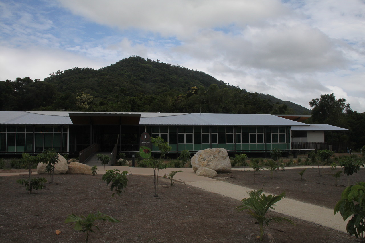
ポートダグラス
mossman gorge centre
皆既日食特集新聞が置いてありました。
皆既日食について詳しく説明しています。
どこのビーチで見るのが一番良いか説明しています。
やはり4マイルビーチが有力です。中央の一番でかい写真です。
ここで前回日食があったのはAD 710年だそうで、
次の日食は25万2237年4月まで見られないそうです。
ダグラスのいくつかの展望台は閉鎖されます。
警察がCook Higtwayをパトロールします。
展望場所や駐車場は車でいっぱいになるでしょう。
当日の朝、日食専門家(アーストラリア 天文家デビッド レネーク)による無料説明会があります。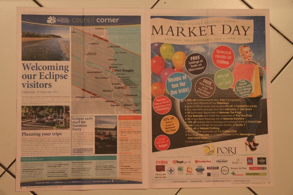
世界中から6万人以上の人が訪れるそうです。
皆既帯の通過地域と皆既継続時間の図が載っています。
我が観測地は皆既帯中心から北に7キロほど離れていますが、
ほぼベストポジションです。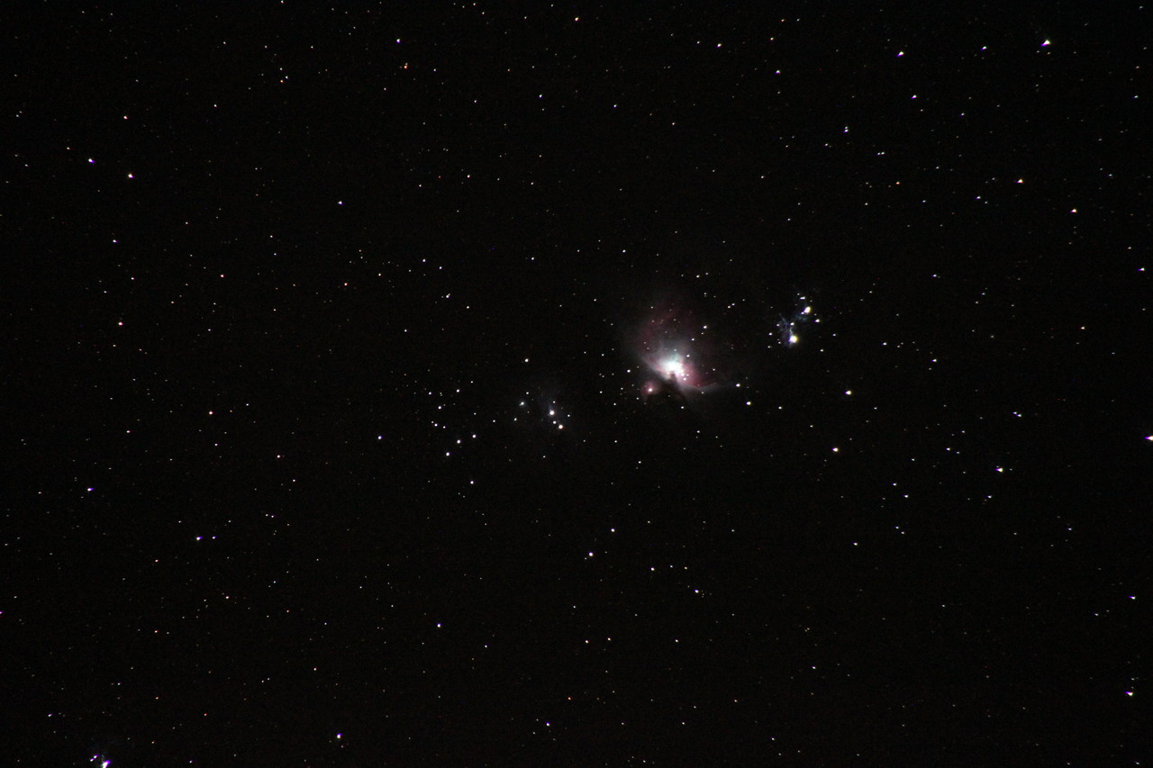
11月9日夜のオリオン大星雲M42です。
270mmF6.3で30秒露出。
拡大して見ると蝶の羽の様な形とピンク色が良くわかります。